A heat pump is a device that transfers heat energy from a source of heat to a destination called a heat sink. For people who prefer to see an actual wiring schematic or diagram when wiring up a room thermostat those illustrations are provided here to help understand what wires are being connected and what each wire is doing.
 Home Heat Pump Wiring System Wiring Diagram
 Payne package unit wiring diagram luxury carrier package unit.

Heating wiring diagrams. Heating only thermostat wiring diagrams if you only have a furnace such as a gas furnace oil furnace electric furnace or a boiler then you will use the following for simple thermostat wiring. C is known as the common terminal. Faq wiring diagram s plan pump overrun st9420 and dt92e faq wiring diagram s plan plus pump overrun st9420 and dt92e faq wiring diagram combination boiler st9120 honeywell t4 additional wiring diagrams lyric t6 additional wiring diagrams v4043 zone valve s plan operation heating controls wiring guide issue 17.
The color of wire r is usually red and c is black. Assortment of trane heat pump wiring diagram. A wiring diagram is a simplified standard photographic depiction of an electrical circuit.
Air conditioner thermostat wiring diagram sample. This originates from the transformer. These two connections will ensure that there is power to the.
Thermostat wiring colors and terminals. A collection of heat pump diagrams are available in the following printable diagramsthe images that we have collected below show the illustrations on how to make a heat pump installation wiring and work. Terminal r or terminal rh for the red wire.
5 ton goodman heat pump circuit and schematic wiring package unit. It reveals the parts of the circuit as simplified shapes as well as the power and also signal links between the tools. It reveals the parts of the circuit as simplified shapes and the power and also signal links between the gadgets.
A wiring diagram is a simplified standard pictorial representation of an electrical circuit. Heat pump thermostat wiring a typical wire color and terminal diagram. Goodman heat pump package unit wiring diagram gallery goodman heat pump package unit wiring diagram new lennox thermostat.
This article provides room thermostat wiring diagrams for flair honeywell white rodgers and other thermostat brands. Heat pump thermostat wiring chart diagram hvac the following graphics are meant as a guide only. Additional articles on this site concerning thermostats and wiring can help you solve your problem or correctly wire a new thermostat.
Always follow manufacturers instructions for both the thermostat and the hvac system. As shown in the diagram you will need to power up the thermostat and the 24v ac power is connected to the r and c terminals. Variety of goodman heat pump wiring schematic.
Wiring Diagram For Uponor Underfloor Heating Wiring Diagram  Wiring Diagram For Boiler System Wire Management Wiring Diagram
 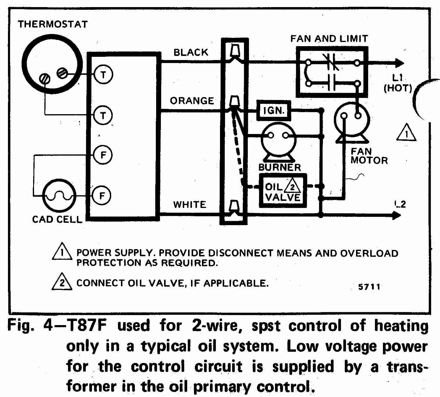 Heat Wiring Diagrams Wiring Diagram Fascinating
  Wire Diagram For Thermostat Toolbox Wiring Diagram
  Armstrong Ac Heat Strip Wiring System Wiring Diagram
  Wiring Diagram For Underfloor Heating Wiring Diagram Fascinating
  Wiring Diagram For Underfloor Heating And Radiators System Wiring
  Y Plan Central Heating System
  Danfoss Underfloor Heating Wiring Centre Diagram Wiring Diagram