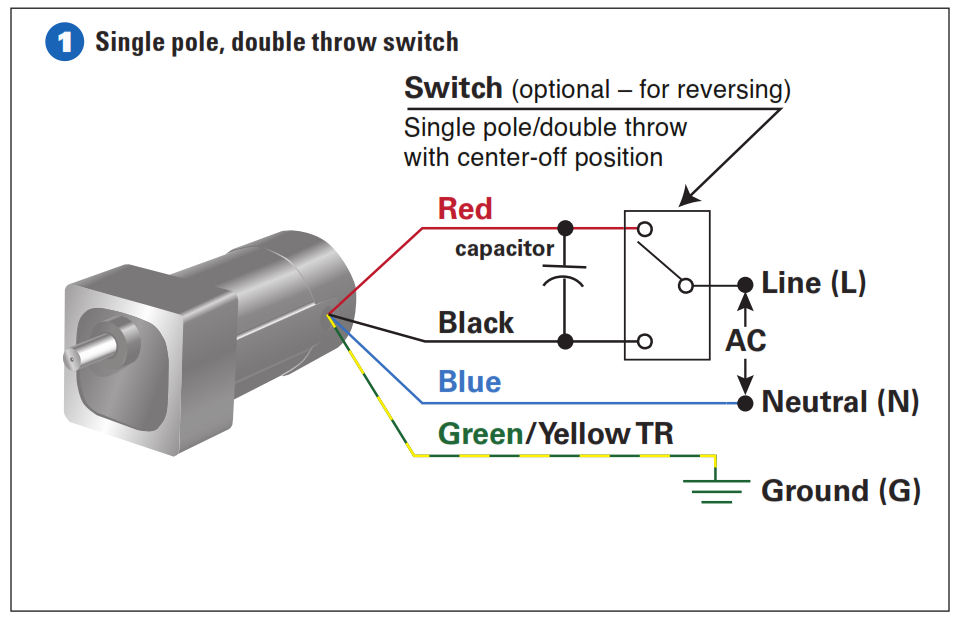
In the above one phase motor wiring i first connect a 2 pole circuit breaker and after that i connect the supply to motor starter and then i do cont actor coil wiring with normally close push button switch and normally open push button switch and in last i do connection between capacitor. You will find out how to identify to main and auxilliary winding and change motor rotation.
 240 Volt Motor Wiring Diagram Wiring Diagram Img
 Click here to view a capacitor start motor circuit diagram for starting a single phase motor.

Electric motor wiring diagrams single phase. Reverse baldor single phase ac motor circuit diagram carvetools. Baldor reliance industrial motor wiring diagram new wirh baldor. Terminal markings and internal wiring diagrams single phase and polyphase motors meeting nema standards b.
W2 cj2 ui vi wi w2 cj2 ui vi wi a cow voltage y high voltage z t4 til t12 10 til t4 t5 ali l2 t12 ti blu t2 wht t3org t4 yel t5 blk t6 gry t7 pnk t8 red t9 brk red tio curry tii grn t12 vlt z t4 til t12. Wiring a motor for 230 volts is the same as wiring for 220 or 240 volts. Residential power is usually in the form of 110 to 120 volts or 220 to 240 volts.
Single phase motors are used to power everything from fans to shop tools to air conditioners. Baldor single phase motor wiring diagram collections of weg motor capacitor wiring diagrams schematics and baldor diagram in. Learn how a capacitor start induction run motor is capable of producing twice as much torque of a split phase motor.
Wondering how a capacitor can be used to start a single phase motor. Battle of the tools 2394956 views. Three ways to run a three phase motor on single phase and the pros and cons of each method 065 duration.
Capacitor start capacitor run induction motors are single phase induction motors that have a capacitor in the start winding and in the run winding as shown in figure 12 and 13 wiring diagram. Capacitor motor single phase wiring diagrams always use wiring diagram supplied on motor nameplate. How to wire an electrical panel square d duration.
5 hp electric motor single phase wiring diagram beautiful single. Start capacitor run capacitor or permanent capacitor. The above diagram is a complete method of single phase motor wiring with circuit breaker and contactor.
Some motors allow both 120 volt and 240 volt wiring by providing a combination of wires for doing so. This type of motor is designed to provide strong starting torque and strong running for applications such as large water pumps. Also read about the speed torque characteristics of these motors along with its different types.
If a single phase motor is single voltage or if either winding is intended for only one voltage the terminal marking shall be determined as follows. How to wire single phase motor with capacitor. Single phase motor wiring diagrams single voltage motor 208 230v ccw cw l2 l1 t1 t8 t4 t5 t1 t5 t4 t8 dual voltage motor 115v or 208 230v 208 230v or 460v low voltage high voltage ccw cw ccw cw l2 t1 t3 t8 t2 t4 t5 t1 t3 t5 t2 t4 t8 l1 t1 t3 t8 t2 t4 t5 t1 t3 t5 t2 t4 t8 l1 l2 dual voltage motor with manual overload mo 115v or 208 230v 208.
Weg motor capacitor wiring diagrams schematics and baldor diagram in.
 110 220 Volt Single Phase Motor Wiring Diagram Wiring Diagram Review
  Baldor Single Phase Wiring Diagram Mncenterfornursing Com
  Baldor 5hp Motor Wiring Diagram Mncenterfornursing Com
  Electric Motor Single Phase Wiring Diagram Elegant Wiring A Single
  Wiring Diagram Single Phase Electric Motor 115 Volts Wiring
  Baldor Motor Wiring Diagrams Single Phase Wiring Diagram Local
  Wiring Diagram Single Phase Electric Motor 115 Volts Electrical
  240v Ac Motor Diagram Wiring Diagrams Dash
  Single Phase Reversing Switch Diagram Schema Wiring Diagram